
News Centre
News Type
Send your inquiry
PTFE RF Insulation: High-Frequency Design Guide
Why PTFE RF Insulation Dominates High Frequencies
Radio frequency systems place brutal demands on insulating materials. At gigahertz frequencies, ordinary plastics absorb signal energy and distort impedance. PTFE RF insulation avoids those losses because polytetrafluoroethylene has one of the lowest dielectric constants and dissipation factors of any solid polymer. With a Dk near 2.05 and a dissipation factor below 0.0003 at microwave frequencies, PTFE lets signals travel with minimal attenuation.
In addition, the insulator geometry interacts with the dielectric constant. A thicker wall lowers capacitance, while a thinner wall raises it. Therefore, designers tune dimensions to reach the target impedance. Small adjustments produce measurable changes at high frequency.
Furthermore, those electrical values stay stable across temperature and frequency. This consistency matters for impedance-matched components such as connectors, adapters, and antenna feeds. When an engineer measures a return loss specification at 28 GHz, the insulator must behave identically on a hot rooftop and a cold tower. PTFE‘s low moisture absorption, under 0.01 percent, also prevents the dielectric drift that humid air causes in other materials.
Furthermore, designers should verify the loss tangent at the operating frequency. In addition, this data should correspond to the actual material lot used for the parts.
Dielectric Properties at Millimeter-Wave Frequencies
The switch to 5G and millimeter-wave bands pushed dielectric requirements higher. At 28 GHz and above, even small losses become unacceptable because they convert directly into heat and shorter range. PTFE RF insulation keeps the dissipation factor low across this entire band. In contrast, many thermoplastics show rising loss at high frequency, which forces designers to avoid them in the signal path.
Moreover, PTFE‘s low moisture uptake protects performance in humid air. Water has a high dielectric constant, so any absorbed moisture raises losses. In contrast, PTFE absorbs almost nothing. Outdoor and coastal installations stay stable.
The dielectric constant also determines physical size. Because Dk is low, a PTFE insulator must be larger than a ceramic one for the same impedance. However, that trade-off is acceptable in many connector designs. Moreover, PTFE‘s consistency means the impedance of a batch of connectors varies little from part to part, a critical property for production RF hardware. Manufacturers therefore accept the size penalty to gain repeatable electrical performance.
Machining PTFE Insulators and Support Components
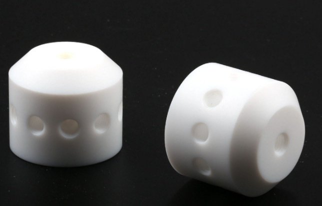
RF insulators are often small, precise parts machined from PTFE rod or tube. Support beads, spacers, and standoffs must hold tight tolerances while remaining soft enough not to stress the center conductor. PTFE machines well with sharp tooling, but it is soft and can smear if feeds are wrong. In addition, the material’s high thermal expansion means machined dimensions should be measured at a controlled temperature.
For example, connector manufacturers qualify PTFE lots before production. They measure density and dielectric properties on every batch. Furthermore, traceability from the resin to the finished insulator supports quality claims. This discipline keeps high-volume parts consistent.
Surface finish influences performance at high frequency. A smooth, clean insulator surface reduces corona and partial discharge in high-power systems. Furthermore, PTFE is naturally non-wetting, so moisture and contaminants do not cling to the surface. For high-reliability aerospace and telecom parts, many manufacturers specify PTFE machined by suppliers who understand RF tolerance requirements. NAGOMER machines PTFE insulators and supplies rod, tube, and sheet stock for RF workshops.
Grades of PTFE for RF Components
Not all PTFE behaves identically. Virgin PTFE offers the best electrical consistency and is the standard for RF insulation. However, some components need more rigidity than virgin PTFE provides. Glass-filled PTFE raises compressive strength and reduces creep, but the added filler can slightly increase loss. Therefore, support parts away from the signal path often use filled grades while the critical insulator stays virgin.
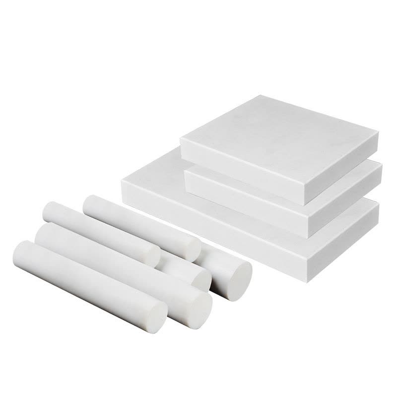
In addition, the manufacturing route affects properties. Skived film, molded rod, and extruded tube each have a different microstructure. Molded rod tends to be densest and most consistent for precision machining. Furthermore, buyers should verify density because porosity changes the dielectric constant. A reputable PTFE supplier documents density and electrical data for every lot, letting RF engineers trust their impedance calculations.
For example, a dense void-free rod machines into insulators with repeatable dimensions.
RF Applications and Sourcing Advice
PTFE appears throughout the RF chain. Coaxial connector insulators, antenna feed supports, filter tuning elements, and waveguide spacers all rely on PTFE RF insulation. In addition, PTFE is used in radar systems, satellite ground stations, and test equipment where loss must stay minimal. The material also resists the ozone and UV exposure common on outdoor antennas.
Meanwhile, prototyping with machined PTFE speeds up development. Engineers can test several geometries without tooling investment. In addition, NAGOMER provides rod and tube in the needed diameters. Custom machining completes the loop.
For development teams, working with a machinist who stocks multiple PTFE grades shortens the prototyping loop. NAGOMER Engineering Plastics, nagomer.com, supplies virgin and filled PTFE rod, tube, and sheet with documented density and offers custom machining of RF insulators and supports for the telecom industry.
Need stable RF insulators at microwave frequencies? NAGOMER supplies PTFE rod, tube, and machined parts. Email info@nagomer.com for dielectric data and custom quotes.